- Home
- Machine
- Media
- Application
- Service
- About Us
- Blogs
- Contact Us
- All
- Product Name
- Product Keyword
- Product Model
- Product Summary
- Product Description
- Multi Field Search


Views: 0 Author: Site Editor Publish Time: 2026-07-28 Origin: Site
Surface damage, edge chipping, and impingement marks during mass finishing directly erode profit margins and increase scrap rates for high-value manufactured components. Achieving the optimal balance between batch throughput and part protection is a daily challenge on the production floor. Operators must establish a media matrix in a vibratory polishing machine that effectively cushions components without severely bottlenecking production capacity. Defining the exact media-to-part loading ratio by volume is the only verifiable method to eliminate part-to-part contact while maintaining finishing efficiency. You must adjust this ratio based on machine dynamics, part geometry, compound chemistry, and media wear to ensure consistent results. Relying on guesswork leads to damaged parts and wasted processing time.
Impingement occurs when parts collide with enough force to dent, scratch, or deform the surface. Surface nesting happens when flat components stick together, preventing media from finishing the masked areas. In mass finishing, success is defined as zero metal-on-metal contact throughout the entire duration of the vibratory cycle. The media matrix acts as both a cutting tool and a physical suspension system. Under vibration, this matrix behaves like a high-viscosity fluid. It carries parts in a continuous rolling motion.
Parts migrate through the media mass at different speeds due to density, geometry, and buoyancy differences. Heavy components sink faster than lightweight plastic media. Large parts displace more media, altering the local flow dynamics. If the ratio is too low, these migration differences lead to inevitable collisions. Operators can detect insufficient ratios during operation through acoustic and visual indicators. Metallic clinking sounds often signal direct part-to-part contact. Parts pooling on the surface of the media bed indicate poor suspension and an inadequate media volume. You need to watch the roll of the mass. A healthy roll turns over smoothly, pulling parts down into the center and pushing them up the sides. When the ratio drops, the mass looks sluggish. Parts start riding on top instead of mixing into the media.
Understanding the suspension mechanics requires looking at the energy transfer from the motor to the tub. The eccentric weights generate a specific amplitude and frequency. This energy transfers through the polyurethane lining into the media. The media pieces push against each other, creating a fluid-like state. When you introduce parts into this environment, they disrupt the energy flow. A heavy steel casting absorbs more energy than a small aluminum bracket. The media must surround the casting completely to absorb the impact forces. If the media volume is too low, the casting pushes through the media layer and strikes the tub wall or another casting. This is why the volume of the media must overwhelmingly exceed the volume of the parts.
The industry-standard starting point is a 3:1 to 4:1 media-to-part ratio by volume. This baseline works well for durable parts like steel stampings and robust castings where minor contact is less critical. However, high-value and fragile components require much higher ratios. Aerospace, medical, or precision-machined parts with tight tolerances or delicate edges often need 6:1, 8:1, or even 10:1 ratios to guarantee complete isolation. You cannot afford a single scratch on a titanium bone plate or a turbine blade.
You must always calculate loading ratios by volume, never by weight. A 4:1 ratio by weight fails completely when mixing high-density steel parts with low-density plastic media. The steel will overwhelm the plastic volume, leading to immediate part damage. To evaluate total working capacity, you need to understand bulk density. The formula is simple: Bulk Density = Weight of Media / Volume of Vessel. Once you know the bulk density, you can calculate the total charge. Determine the physical liters or cubic feet of media needed for a specific batch size of parts inside the processing tub to ensure a proper volumetric ratio.
Let us break down the calculation process for a standard production run. First, determine the usable volume of your machine. Most manufacturers recommend filling the tub to 80% or 90% of its total capacity. If you have a 300-liter tub, your working volume is roughly 250 liters. Next, decide on your target ratio. If you are processing machined aluminum valve bodies, you might select a 5:1 ratio. This means you need five parts media to one part components by volume. Out of your 250-liter working volume, approximately 208 liters will be media, and 42 liters will be parts. You then measure your parts in a calibrated bucket to ensure you do not exceed that 42-liter limit per batch. This volumetric approach guarantees the physical space between parts remains consistent, regardless of how heavy the parts or the media are.
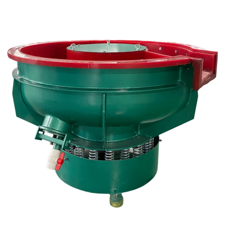
The fluid dynamics of your equipment heavily dictate your ratio requirements. A vibratory bowl finishing machine relies on a toroidal, or corkscrew, rolling action. This motion disperses parts outward and downward. The depth of the bowl channel directly affects part suspension. Heavy parts tend to sink toward the polyurethane lining, requiring deeper media beds to maintain a cushion. You must also monitor the waterfall zone where parts cascade down the spiral ramp, as this is a high-risk area for collisions. The drop off the ramp can cause parts to slam into each other if the media does not provide enough padding at the bottom of the step.
Linear tub-style machines operate differently. A trough vibratory finishing machine generates a straight-line rolling action. Long, heavy, or awkwardly shaped parts like camshafts or aerospace spars require higher media ratios here to prevent end-to-end collisions. Sometimes, operators use physical polyurethane or rubber dividers as a mechanical supplement to high loading ratios in these tubs. The dividers create individual compartments, ensuring that a long shaft cannot slide down the length of the tub and strike another shaft. Even with dividers, you still need enough media to prevent the part from hitting the divider walls too hard.
Using a vibratory machine with separator introduces another variable. Internal separation decks temporarily alter the media-to-part ratio. As media falls through the screen, parts are left exposed. You must account for this volume shift to prevent contact at the discharge gate. Adjusting dam gates and screen sizes helps manage the transit speed of parts during the separation cycle. If the parts move too fast across the screen, they bunch up at the exit chute. You need to tune the machine weights to slow down the forward feed during separation, allowing the parts to exit one by one rather than in a massive cluster.
Part geometry and density drastically change how components behave in the machine. Flat parts tend to stick together, a phenomenon known as nesting. Heavy parts migrate to the bottom of the channel. Internal cavities, blind holes, or complex internal channels trap media. This reduces the active media volume in the tub, requiring a higher starting ratio to compensate for the trapped material. If a part has a large cup shape, it will scoop up media and hold it. That media is no longer helping to cushion the rest of the batch.
Media size, shape, and bulk density also affect the protective matrix. Smaller media shapes like cones and pyramids provide better cushioning and part encapsulation. Larger media shapes like large triangles leave gaps where part-to-part contact can occur. Heavy ceramic media offers a different cushioning profile compared to lightweight plastic or synthetic media. Ceramic transfers more cutting energy but requires a stronger motor to maintain the roll. Plastic media is lighter and provides a softer cushion, making it ideal for aluminum or zinc die castings.
Machine aggressiveness correlates directly with ratio requirements. Higher amplitude settings create more violent action and greater displacement. You need a higher volume of media to act as a shock absorber under these conditions. Finally, liquid compounds and water flow rates alter the viscosity of the media mass. High flow rates can cause hydroplaning or rapid sinking of heavy parts. Low flow rates increase friction, slowing down the toroidal movement and increasing the risk of part clustering. The compound acts as a lubricant. If you run the machine too dry, the media locks up and stops rolling. If you run it too wet, the media washes out and loses its cutting ability.
| Part Type | Recommended Media Type | Starting Volumetric Ratio | Primary Risk Factor |
|---|---|---|---|
| Steel Stampings | Ceramic Triangles | 3:1 to 4:1 | Nesting of flat surfaces |
| Machined Aluminum | Plastic Cones | 5:1 to 6:1 | Edge chipping |
| Aerospace Components | High-Density Synthetic | 8:1 to 10:1 | Surface impingement |
| Heavy Castings | Large Ceramic Cylinders | 4:1 to 5:1 | Sinking to the tub lining |
| Medical Implants | Porcelain Spheres | 10:1 | Micro-scratching |
To manage these variables effectively, operators should follow a strict evaluation protocol before running a new part. This involves several distinct steps to ensure the process remains stable.
Running excessively high ratios creates an economic burden. If you use a 12:1 ratio for a part that only needs 4:1, you face increased cycle times and reduced parts per batch. This over-cushioning leads to higher energy consumption and accelerated media wear. You are essentially paying to run a machine full of media with very few parts in it. This drives up the cost per piece and reduces your overall factory output. However, the cost of under-cushioning is often worse. Low ratios result in manual rework labor, rejected parts, and compromised structural integrity of critical components. Scrapping a batch of aerospace parts because of impingement marks costs far more than running a slightly longer cycle with a higher media ratio.
Finding the sweet spot requires a systematic ROI framework. Start by running controlled sample batches. Begin at a high ratio, such as 8:1. Systematically reduce it in small increments down to 6:1, 5:1, and 4:1. Stop at the first sign of surface contact. Inspect the parts under adequate lighting to check for micro-dents or rolled edges. Once you identify the failure point, add a 15% safety margin to establish your final production specification. This safety margin accounts for normal media wear during a production shift. If the failure point is 4:1, set your production standard at 4.6:1 or 5:1 to ensure consistent quality.
Media attrition is a silent threat. As media wears down and flushes out as sludge, the overall volume drops. A safe 5:1 ratio can easily degrade into a dangerous 3:1 ratio mid-production. Mitigate this by implementing strict daily volume checks. Use standard height line markers on the interior polyurethane lining of the machine. Automated media top-off systems also help maintain consistent volumes. Operators should visually inspect the media level at the start of every shift. If the level drops below the marker line, they must add fresh media before loading any parts.
Improper loading sequences cause immediate impingement damage. Dumping parts and media simultaneously, or loading parts into an empty machine, guarantees collisions. Establish standard operating procedures for layering. Fill the machine with the base media charge first. Initiate the vibration and water flow, then feed parts incrementally at the correct rate. Part entanglement is another risk, especially for hook-like parts. Use mixed-size media configurations or specialized pre-mixing protocols before parts enter the machine to keep them separated. You can also use automated part feeders that drop components into the mass at timed intervals, ensuring they disperse evenly throughout the media bed.
A: The industry standard starting point is a 3:1 or 4:1 ratio by volume for durable parts. However, fragile or high-precision components often require ratios between 6:1 and 10:1 to ensure complete isolation and prevent impingement.
A: Different media types have vastly different bulk densities. A 4:1 ratio by weight using heavy steel parts and light plastic media would result in an insufficient volume of media, failing to cushion the parts and leading to immediate damage.
A: Damage at higher ratios usually indicates issues with part geometry, such as heavy parts sinking to the bottom, or improper machine settings. High amplitude or insufficient compound flow can disrupt the media matrix, allowing parts to collide.
A: Yes, often it does. The linear action of a trough machine can cause long or awkwardly shaped parts to migrate and collide end-to-end. Higher media volumes, or physical dividers, are frequently needed to maintain separation.
A: Media volume should be checked daily. As media wears down into sludge, the total volume decreases. Implementing a daily top-off protocol ensures the ratio remains consistent and prevents sudden part-to-part contact mid-production.
A: Prevent nesting by using a higher media-to-part ratio and selecting a mixed-size media configuration. Smaller media shapes help penetrate between flat surfaces, keeping them separated and ensuring uniform finishing across the entire part.